7 Steps Involved in PEB Manufacturing
PEB manufacturing is the factory process that turns a client’s brief into a numbered kit of steel members ready to bolt together on site. It runs in seven steps: engineering design to the Indian codes, detailing and shop drawings, material procurement and inspection, CNC cutting and drilling, fitting and welding of the built-up sections, shot blasting and painting, and roll-forming, marking, bundling and dispatch. Each step ends in a check with a record against the member’s mark number, which is why a pre-engineered building arrives on site fitting the drawing. DSI runs all seven under one roof at Chhattar, Rajkot, and ships a standard building in under six weeks from approved drawings.
What is the PEB manufacturing process?
A pre-engineered building is made before it is built. Its frames, purlins, girts, sheeting and accessories are engineered, fabricated and numbered in a factory, then delivered to site as a kit and bolted together in a planned sequence. The manufacturing process is everything that happens between the client’s brief and the loaded trailer, and it is where the quality of the finished building is decided. A frame that was designed to the wrong wind speed, cut to the wrong length or painted too thin cannot be corrected by the erection crew.
The process is the same for every PEB manufacturer in principle and very different in practice. What follows is the sequence as DSI runs it at its 15,000 square metre works at Chhattar, on the Rajkot–Morbi highway: seven steps, each ending in a check with a record, from the first engineering calculation to the dispatch note. If you are comparing manufacturers, these are the seven things to ask to see.
- Requirement review and engineering design: the frame is designed for the site and the operation to the Indian codes.
- Detailing and shop drawings: every member is drawn for the shop and marked for the site.
- Material procurement and inspection: plate, sheeting and bolts are bought to the design grades and checked against their certificates.
- Cutting and drilling: webs, flanges and plates are cut on CNC lines and holes are drilled or punched to the model.
- Fitting and welding: flanges and webs become built-up tapered sections on the automatic welding line.
- Surface preparation and painting: members are shot-blasted, primed and painted to a measured thickness.
- Roll-forming, marking, bundling and dispatch: purlins, girts and sheeting are formed, and the whole building is numbered and loaded in erection order.
Step 1: Requirement review and engineering design
Manufacturing starts at a desk. An engineer reads the brief: the use of the building, its length, width and eave height, the site location, the cranes, mezzanines and equipment it carries, and how the business expects to grow. From the location come the design loads. Wind is taken from IS 875 Part 3 for the basic wind speed of the place and the terrain around it. Seismic load follows IS 1893 for the zone. Dead, live and collateral loads cover the steel, the sheeting, the insulation, the sprinkler mains, the cable trays and the solar panels the roof will carry. Crane loads add wheel loads, surge and fatigue to the columns and brackets.
With the loads fixed, the frame is analysed and designed to IS 800, the Indian code for structural steel. Each column and rafter is a built-up I-section whose web depth is tapered to follow the bending moment, so steel sits where the load is and is saved where it is not; that is what makes a PEB frame 20 to 30% lighter than a conventional hot-rolled frame. Clear spans to 50 m and bays of 8 to 10 m are routine, and crane brackets for electric overhead travelling cranes to 50 MT are designed into the columns from the start. The output of this step is the design basis and the general arrangement drawings, which the client reviews and approves before anything else moves.
Step 2: Detailing and shop drawings
Once the general arrangement drawings are approved, detailing turns the design into instructions for the shop. Every member is modelled and drawn: the plate thicknesses and widths of each flange and web, the taper, the stiffeners, the end plates and base plates, the position and diameter of every bolt hole, the welds and their sizes, and the camber where the span needs it. Connections are standardised so that the same bolt group appears at every haunch and ridge, and each member receives a mark number that follows it from the cutting list to the erection drawing.
Two drawings leave this step for the site before the steel does. The anchor bolt setting-out drawing goes to the civil contractor, so the foundations can be cast while the steel is being made, with the bolts in templates to the dimensions the columns will need. The erection drawings show every mark number in position, in the sequence the frames will be raised. The rest of the detailing output stays in the shop: nesting programmes for the CNC cutters, cutting lists, drilling files and a bill of materials that drives the next step.
Step 3: Material procurement and inspection
The bill of materials is bought against the grades the design assumed. For DSI frames that is 345 MPa structural plate for the webs and flanges, S550 high-tensile steel for the roof and wall sheeting, cold-formed sections for purlins and girts, high-strength bolts for the connections, and the coil, insulation and accessories the building needs. Every delivery arrives with a mill test certificate, and inspection checks the certificate against the purchase order and the plate against the certificate: grade, heat number, thickness, flatness and surface condition.
This is the first hold point, and the quietest. Plate that is a grade lower than the design assumed looks exactly like the right plate, cuts and welds the same, and gives a frame that is weaker than the calculation. The certificate and the inspection record are the only proof, and they travel with the building to handover.
Step 4: Cutting and drilling
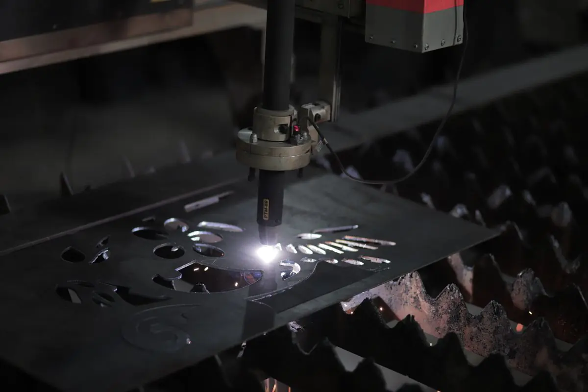
Plate is cut to the nesting programme from detailing. Webs, flanges, stiffeners and gusset plates are cut on the CNC plasma cutting machine, which cuts to the programmed geometry on a 4,000 by 15,500 mm bed, so a full-length tapered web comes off in one piece with its taper exact. Straight flange strips, cleats and flashings are cut to programmed length on the CNC shearing machine, and lighter plate, sheet and trim on the semi-automatic shears. Nesting places the parts on the plate to cut offcut, and the scrap is segregated for recycling.
Holes follow the cut. Bolt holes in end plates, base plates and flanges are drilled on the radial drills, and holes and slots in cleats, plates and cold-formed sections are punched on the hydraulic punching machines, all to the drilling files from the model. Anchor bolts, sag rods and bracing rods have their threads rolled rather than cut, which leaves a stronger thread. The check at the end of this step is dimensional: each cut part against its drawing, and each hole group against its template, so that the bolt groups meet on site without reaming.
Step 5: Fitting and welding
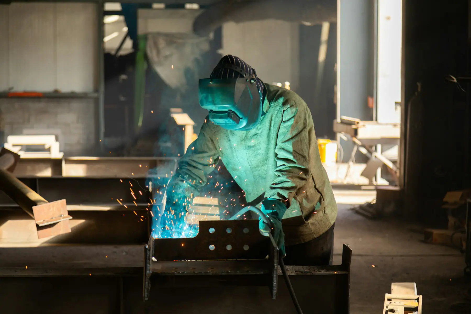
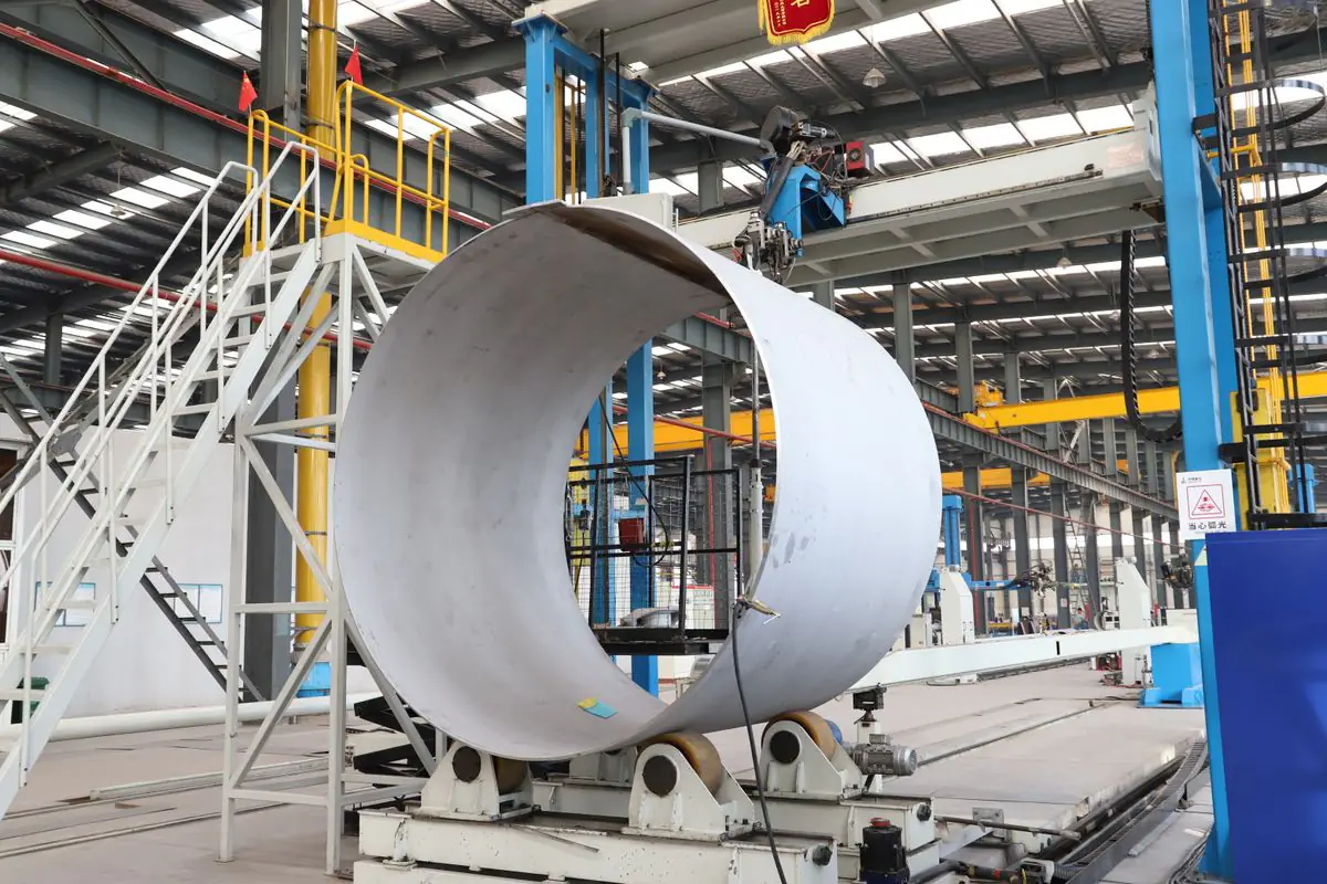
The cut flanges and web are assembled into an I-section. Fit-up sets the web square to the flanges and tacks it in place, with the taper and the camber checked before the main weld. The section then goes through the pull-through automatic welding line, which welds web to flanges in one continuous pass, both sides at once, at a travel speed set for the plate thickness. The automatic line makes the same weld every time, which is the point: a built-up section a metre deep and ten metres long cannot be welded consistently by hand.
The welds the line cannot reach are made on MIG sets: stiffeners, end plates, base plates, crane brackets, cleats and the splice plates. Each welded member is checked visually along its whole length, and non-destructive testing is applied where the design calls for it, at the haunch and the splices where the stress is highest. A trial fit-up of connections before painting is the last check of this step: the end plates of a column and a rafter are brought together and the bolts put through, so that any misalignment is found on the shop floor and not on the crane hook.
Step 6: Surface preparation and painting
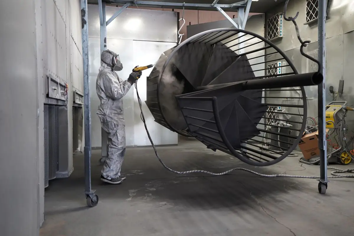
Steel lasts as long as its coating, and a coating lasts as long as the surface under it. Every welded member goes through the shot blasting machine, an enclosed booth where abrasive is thrown at the steel on a conveyor to strip mill scale, rust and weld spatter and to leave a surface profile the primer can grip. The blast standard and the profile are specified in the design and measured on the member before it moves on.
Priming follows the blast within the window the paint system allows, before the fresh surface can begin to oxidise. The primer and the finish coat are chosen for where the building will stand: an inland factory needs a sound primer and a finish; a building near the coast, beside a chemical works or housing a cold store needs a heavier epoxy build, hot-dip galvanised secondary members, or both. Dry film thickness is measured at set points on each member and recorded against its mark number. The galvanised and colour-coated sheeting arrives with its coating already on, chosen for the same exposure.
Step 7: Roll-forming, marking, bundling and dispatch
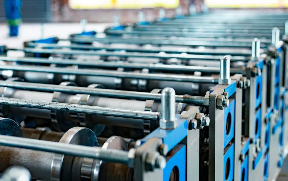
While the primary frames are welded and painted, the rest of the building is formed from coil on the same floor. The C and Z purlins and girts that span between the frames are roll-formed to length on the purlin line, with their holes punched for the cleats and sag rods. The trapezoidal roof and wall sheet is roll-formed from S550 coil in single lengths to order, so the roof has as few end laps as the slope allows. Standing seam roof panels, deck sheet for mezzanine floors, and the flashings, trims, closures and gutters bent on the CNC press brake complete the envelope.
Every member then gets its mark number painted on, matching the erection drawing, and the building is bundled and loaded in the order the site will need it: anchor bolts first if they have not already gone, then the columns and rafters of the first braced bay, the bracing, the purlins and girts, and the sheeting and accessories behind. A packing list ties every bundle to the drawing, and the site checks the load against it when it arrives. For a large building, dispatch is phased, so erection starts on the first bays while the last are still being fabricated.
What happens after manufacturing: erection on site
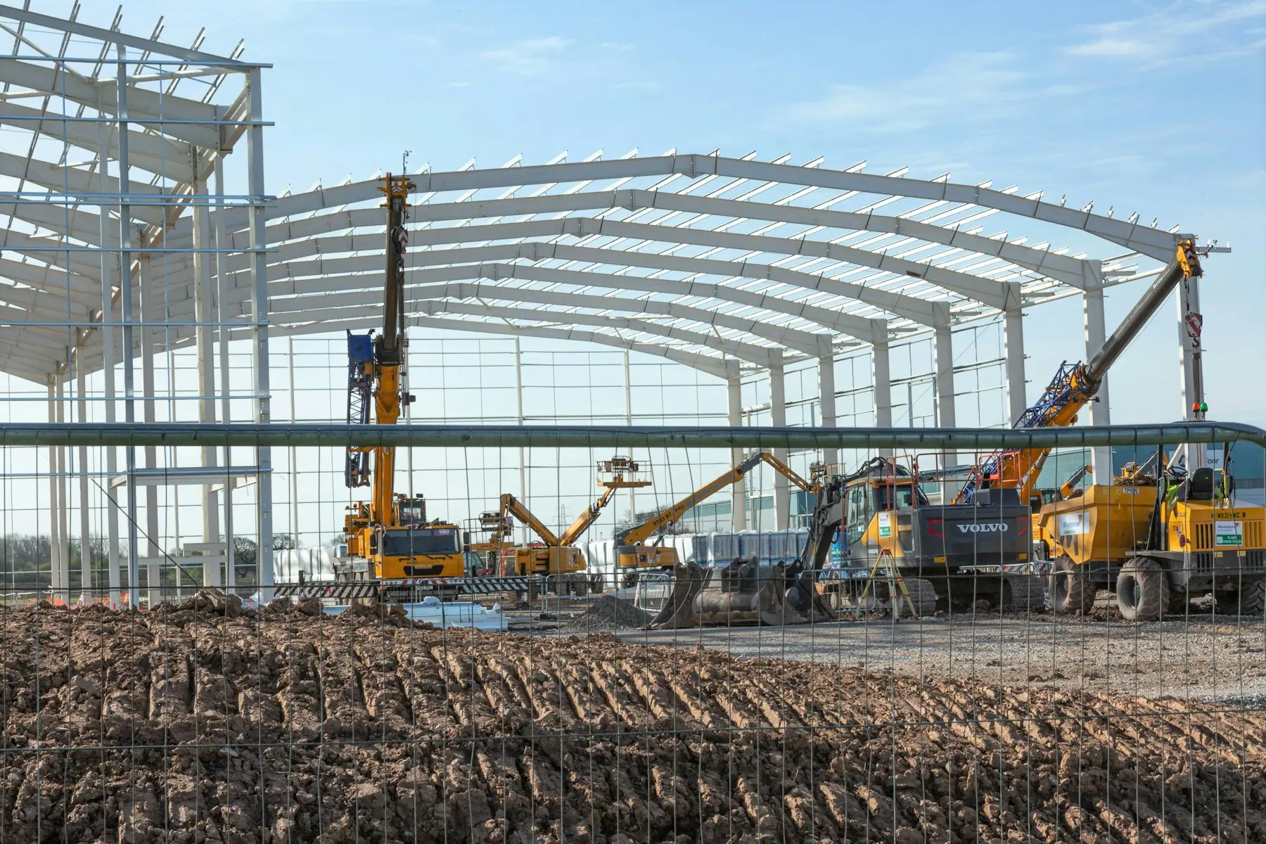
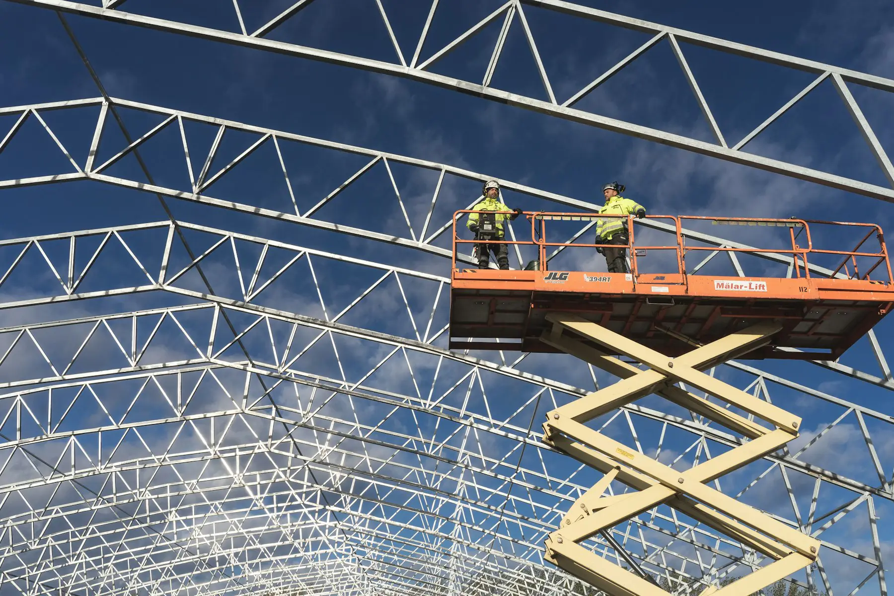
Manufacturing ends at the trailer; the building is finished on site. The foundations have been cast during the fabrication weeks, and the anchor bolts are surveyed against the setting-out drawing before the first lift. The columns of a braced bay go up first and are plumbed, the rafters are lifted and bolted at the haunches and the ridge, the bay is braced before the crane lets go, and the purlins and girts are fixed. The sequence repeats bay by bay, every bolt is torqued and marked, and then the sheeting, insulation, daylight panels, ventilators, gutters and doors follow from the gutters to the ridge. Nothing is cut or welded on site, because steps one to seven made sure nothing needs to be.
The 7 PEB manufacturing steps at a glance
The table sets out each step, what happens in it, the check that closes it and what it hands to the next. The quality checks are the column to keep: they are what a manufacturer should be able to show you for any recent building.
1. Engineering design
- What happens
- Loads from IS 875 Part 3, IS 1893 and the operation; frame designed to IS 800 with tapered built-up sections.
- Quality check
- Design review and client approval of the design basis.
- Output
- Design basis and general arrangement drawings.
2. Detailing and shop drawings
- What happens
- Every member modelled: plates, holes, welds, camber, connections and mark numbers.
- Quality check
- Drawing check against the approved design; connection standardisation.
- Output
- Shop drawings, cutting and drilling files, anchor bolt and erection drawings.
3. Material procurement and inspection
- What happens
- Plate, sheeting, sections, bolts and accessories bought to the design grades.
- Quality check
- Mill test certificates checked against order and plate; thickness and surface inspected.
- Output
- Certified material issued to the shop against the bill of materials.
4. Cutting and drilling
- What happens
- CNC plasma and shearing to the nested programme; drilling, punching and thread rolling to the model.
- Quality check
- Dimensional inspection of parts and hole groups against drawings and templates.
- Output
- Cut and drilled webs, flanges, plates and rods.
5. Fitting and welding
- What happens
- Fit-up, then web-to-flange welding on the automatic line; stiffeners, plates and brackets on MIG sets.
- Quality check
- Visual weld inspection, NDT where specified, trial fit-up of connections.
- Output
- Welded built-up columns, rafters and brackets.
6. Surface preparation and painting
- What happens
- Shot blasting to the specified profile; primer and finish for the site’s exposure.
- Quality check
- Blast profile and dry film thickness measured and recorded per mark number.
- Output
- Coated members ready for marking.
7. Roll-forming, marking and dispatch
- What happens
- Purlins, girts, sheeting, panels and trims formed from coil; members marked, bundled and loaded in erection order.
- Quality check
- Packing list checked against the erection drawing; load checked on site.
- Output
- The complete building kit, dispatched in sequence.
| Step | What happens | Quality check | Output |
|---|---|---|---|
| 1. Engineering design | Loads from IS 875 Part 3, IS 1893 and the operation; frame designed to IS 800 with tapered built-up sections. | Design review and client approval of the design basis. | Design basis and general arrangement drawings. |
| 2. Detailing and shop drawings | Every member modelled: plates, holes, welds, camber, connections and mark numbers. | Drawing check against the approved design; connection standardisation. | Shop drawings, cutting and drilling files, anchor bolt and erection drawings. |
| 3. Material procurement and inspection | Plate, sheeting, sections, bolts and accessories bought to the design grades. | Mill test certificates checked against order and plate; thickness and surface inspected. | Certified material issued to the shop against the bill of materials. |
| 4. Cutting and drilling | CNC plasma and shearing to the nested programme; drilling, punching and thread rolling to the model. | Dimensional inspection of parts and hole groups against drawings and templates. | Cut and drilled webs, flanges, plates and rods. |
| 5. Fitting and welding | Fit-up, then web-to-flange welding on the automatic line; stiffeners, plates and brackets on MIG sets. | Visual weld inspection, NDT where specified, trial fit-up of connections. | Welded built-up columns, rafters and brackets. |
| 6. Surface preparation and painting | Shot blasting to the specified profile; primer and finish for the site’s exposure. | Blast profile and dry film thickness measured and recorded per mark number. | Coated members ready for marking. |
| 7. Roll-forming, marking and dispatch | Purlins, girts, sheeting, panels and trims formed from coil; members marked, bundled and loaded in erection order. | Packing list checked against the erection drawing; load checked on site. | The complete building kit, dispatched in sequence. |
How long does PEB manufacturing take?
The seven steps take a few weeks for a standard building, and they overlap: material is ordered during detailing, cutting starts on the first members while the last are being detailed, and roll-forming runs beside welding. DSI designs, details, fabricates and ships a standard building in under six weeks from approved drawings, from a works with 15,000 MT of annual capacity, and a large building is dispatched in phases so erection can begin before fabrication ends. The full calendar, with the foundations and erection that run around the factory weeks, is in our article on the PEB construction timeline.
How DSI manufactures pre-engineered buildings
Darshan Steel Infrastructure runs all seven steps under one roof at Chhattar, Rajkot, Gujarat: plate in at one end, numbered and painted members out at the other, from a fully enclosed, automated production line. The shop runs to management systems certified by TÜV SÜD to ISO 9001, 14001 and 45001, with inspection hold points recorded against every mark number, and the records are handed over with the as-built drawings and the structural stability certificate. DSI has delivered 230+ buildings across India since 2018 this way.