Main Components of a Pre-Engineered Building
A pre-engineered building is made of five systems that bolt together on site. The primary system is the tapered built-up columns and rafters, end-wall frames, crane brackets and bracing that carry every load to the foundations. The secondary system is the cold-formed purlins, girts and eave struts that span between the frames and carry the sheeting. The cladding system is the roof and wall sheeting with its flashings, trims, gutters and downpipes. Mezzanine floors add a second level inside the frame. Accessories such as insulation, ventilators, daylight panels, louvers, doors and cage ladders complete the building. The foundations, with their anchor bolts, are the interface between the steel and the ground.
What are the main components of a pre-engineered building?
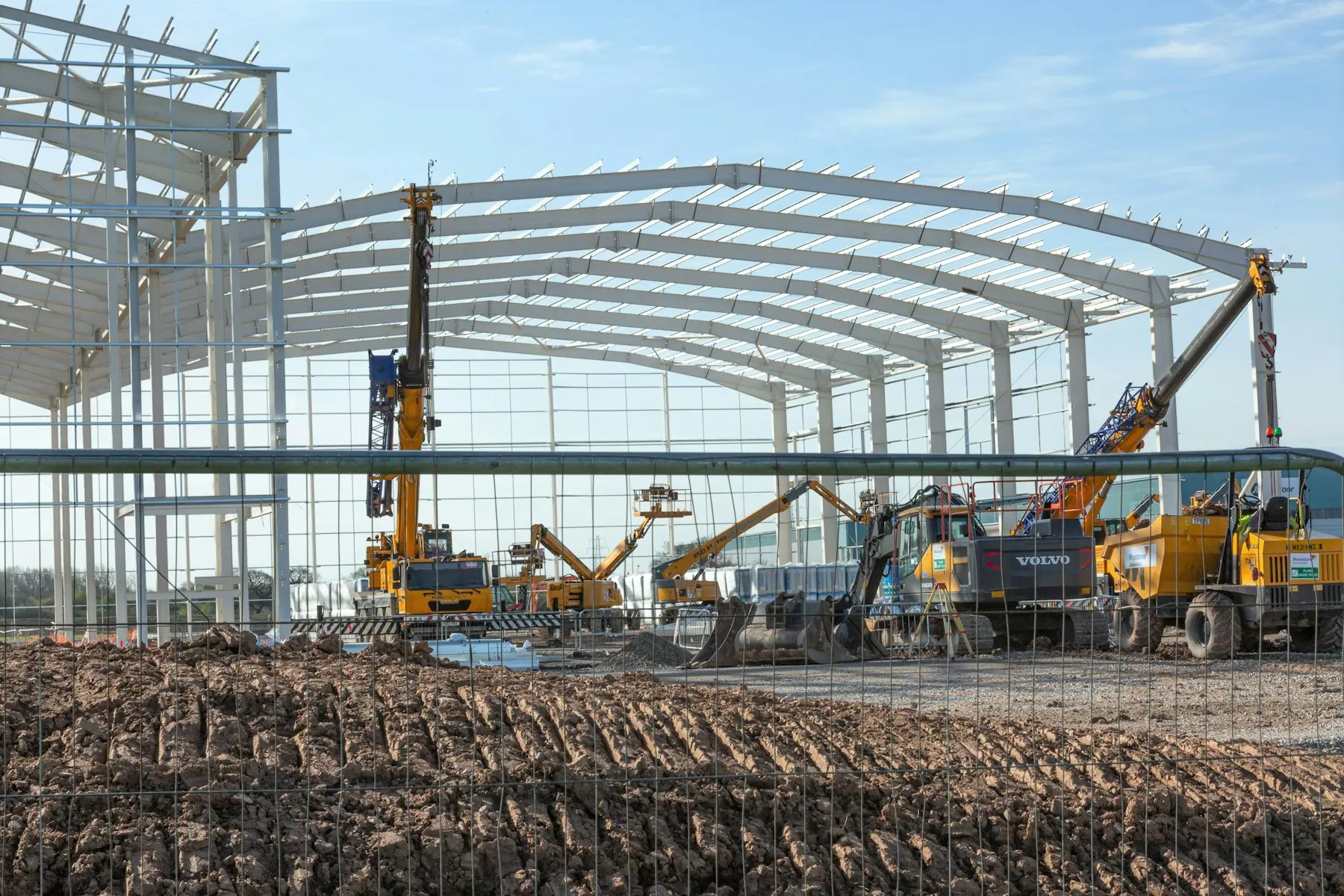
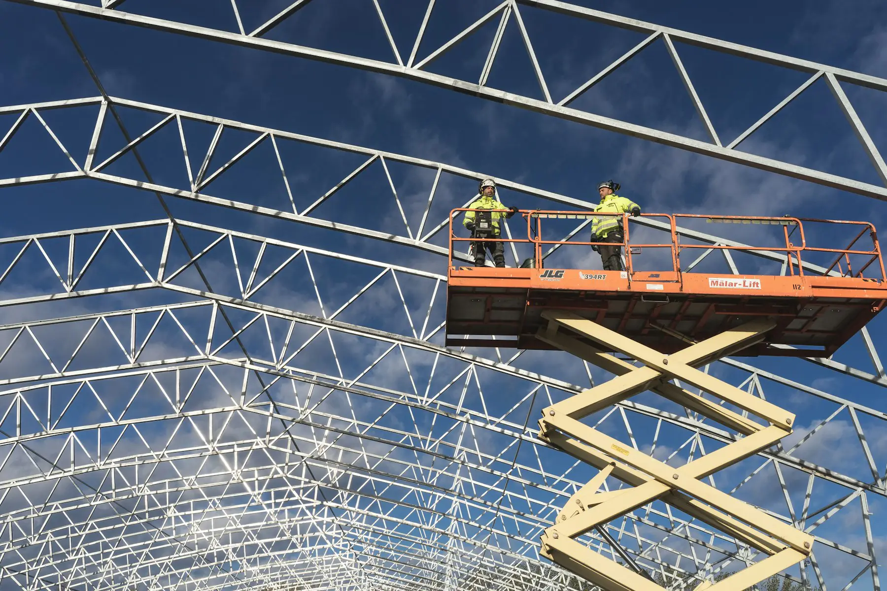
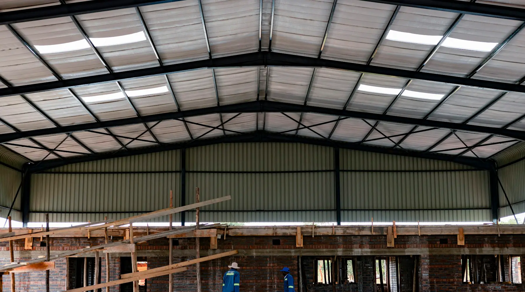
A pre-engineered building looks like one object, a steel shed with a sheeted roof, but it is built from five distinct systems, each with its own members, its own materials and its own job. The primary system is the skeleton: rigid frames of columns and rafters that stand at every bay, end-wall frames that close the ends, brackets for cranes, and the bracing that keeps the frames upright. The secondary system is the ribs: purlins across the roof, girts along the walls and the eave strut where they meet, spanning from frame to frame. The cladding system is the skin: profiled steel sheeting on roof and walls with everything that seals its edges. Mezzanine floors are the optional second level inside the volume. Accessories are what make the sealed box usable: insulation, ventilation, daylight, openings and access.
Underneath all of it are the foundations, which the PEB manufacturer designs the loads for and the civil contractor builds, with anchor bolts cast in to receive the columns. The systems are named in the order the loads travel: from the sheeting to the purlins and girts, from those to the frames, from the frames through the bracing and the base plates to the ground. This guide takes each one in turn, names its parts, and explains what each part does and what it is made of, using the terms a PEB engineer uses on the drawings.
What is the primary framing system of a PEB?
The primary system is every member that carries load to the ground. Its heart is the main frame: a column on each sidewall joined to a pair of rafters that meet at the ridge, with moment-resisting connections at the knees and the ridge so the frame stands on its own without interior columns. The frames repeat along the building at the bay spacing, commonly 8 to 10 m, and DSI frames clear-span to 50 m. Everything else in the primary system either closes the ends, carries a crane or holds the frames in line.
Tapered built-up columns and rafters
PEB columns and rafters are not rolled sections off a stock list. Each is a built-up I-section: a web plate and two flange plates cut to size and welded along their length, with the web depth tapered so the section is deepest where the bending moment is greatest, at the knee of the frame, and shallowest where it is least, towards the ridge and the base. Steel is placed where the load is and saved where it is not, which is why a PEB frame is 20 to 30% lighter than a conventional frame of constant-depth sections. DSI cuts the plate from 345 MPa structural steel on CNC lines and welds the sections on an automatic beam-welding line in the works at Chhattar, Rajkot.
End-wall frames and wind columns
The two ends of the building are closed by end-wall frames. A post-and-beam end wall uses light columns, called wind columns or end-wall posts, at close centres with a rafter that only spans between them; it is the economical choice when the building will never be extended that way. A rigid end wall is a full main frame at the end of the building, with the wind columns only carrying the sheeting, so bays can be added later by unbolting the end sheeting and erecting the next frame. Which end wall to use is a decision taken on the first drawing, because changing it afterwards means new foundations.
Crane brackets and runway beams
Where the building carries an overhead crane, the primary system grows. Crane brackets are welded to the main-frame columns in the shop, and crane runway beams, one on each side of the aisle, rest on them and carry the crane rail with its clips, end stops and bumpers. DSI mounts electric overhead travelling cranes to 50 MT directly on column brackets; heavier cranes get an independent support system with its own columns. The wheel loads, the lateral surge as the trolley brakes and the longitudinal force as the bridge brakes all go into the column, bracket and foundation design, and the runway beam is checked for fatigue over its working life.
Connections, base plates and anchor bolts
The frame is joined on site with high-strength bolts through end plates welded to the members in the shop: a knee connection where the rafter meets the column, and a ridge connection where the two rafters meet. Nothing is welded on site. At the bottom, each column ends in a base plate, drilled to receive the anchor bolts cast into the foundation. A pinned base lets the column rotate slightly and sends only vertical and horizontal force into the footing; a fixed base sends a moment too, which stiffens the frame but needs a bigger foundation. The anchor bolt setting-out drawing is the one document the civil contractor cannot start without.
What does bracing do in a pre-engineered building?
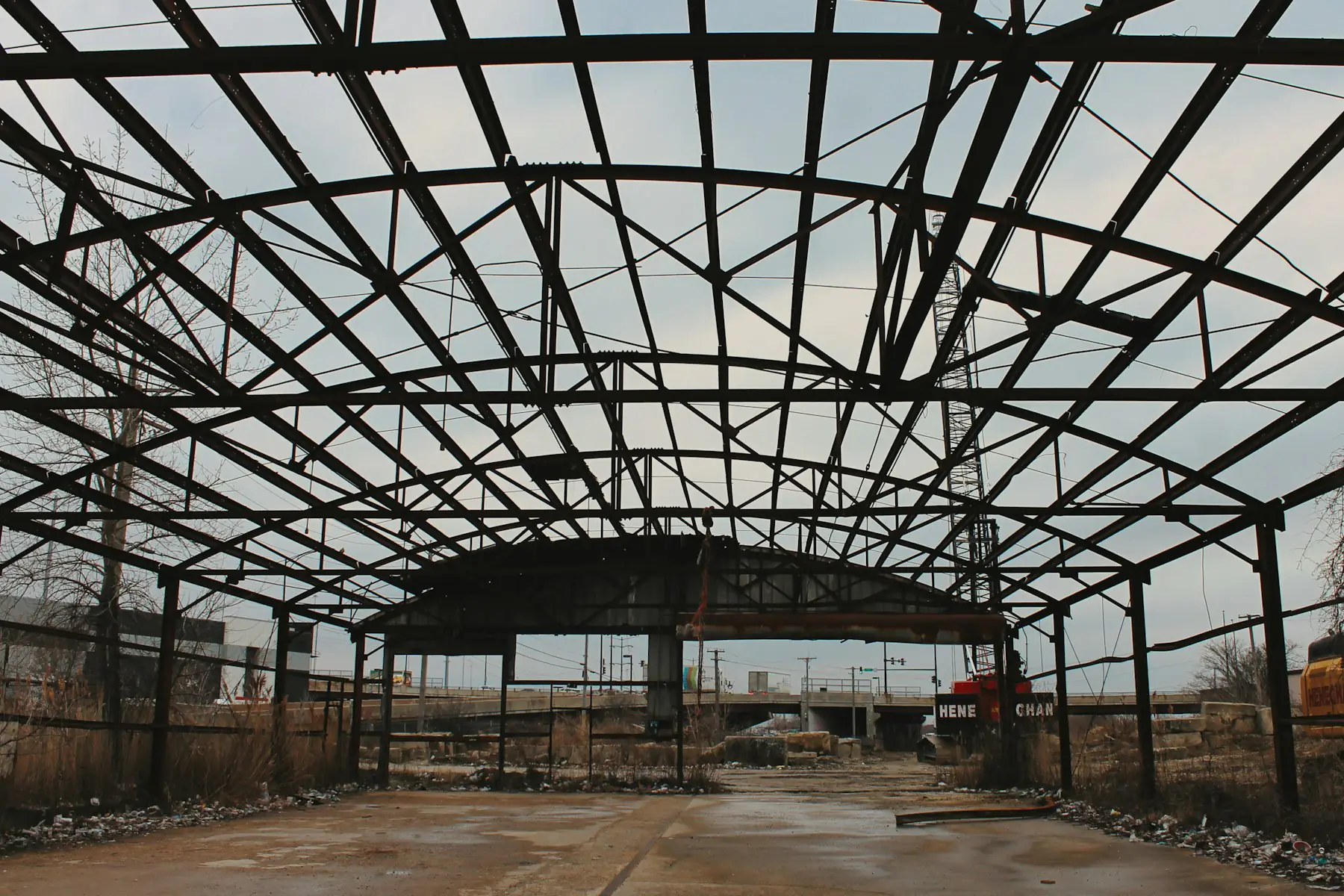
A rigid frame is stiff in its own plane and slender out of it. Bracing supplies the stiffness in the other direction, along the length of the building, and it is part of the primary system because it carries real load: wind on the end walls, crane braking and seismic forces, all of which have to reach the foundations. It also holds the frames upright and square during erection, before the sheeting is on.
- Roof bracing: diagonal rods, cables or angles forming an X in the roof plane of selected bays, turning the roof into a stiff diaphragm.
- Wall bracing: the same X in the sidewall and end-wall bays, from the eave to the column base, with rods and hillside washers or angles.
- Portal bracing: where a door or window leaves no room for a diagonal, a stiff portal frame of built-up members takes its place in the bay.
- Eave struts and ridge struts: longitudinal members tying every frame to the next and completing the load path to the braced bays.
- Flange braces: short angles from the purlins and girts to the inner flange of the rafters and columns, stopping the compression flange buckling sideways, which is what lets the tapered sections stay light.
What are purlins, girts and eave struts?
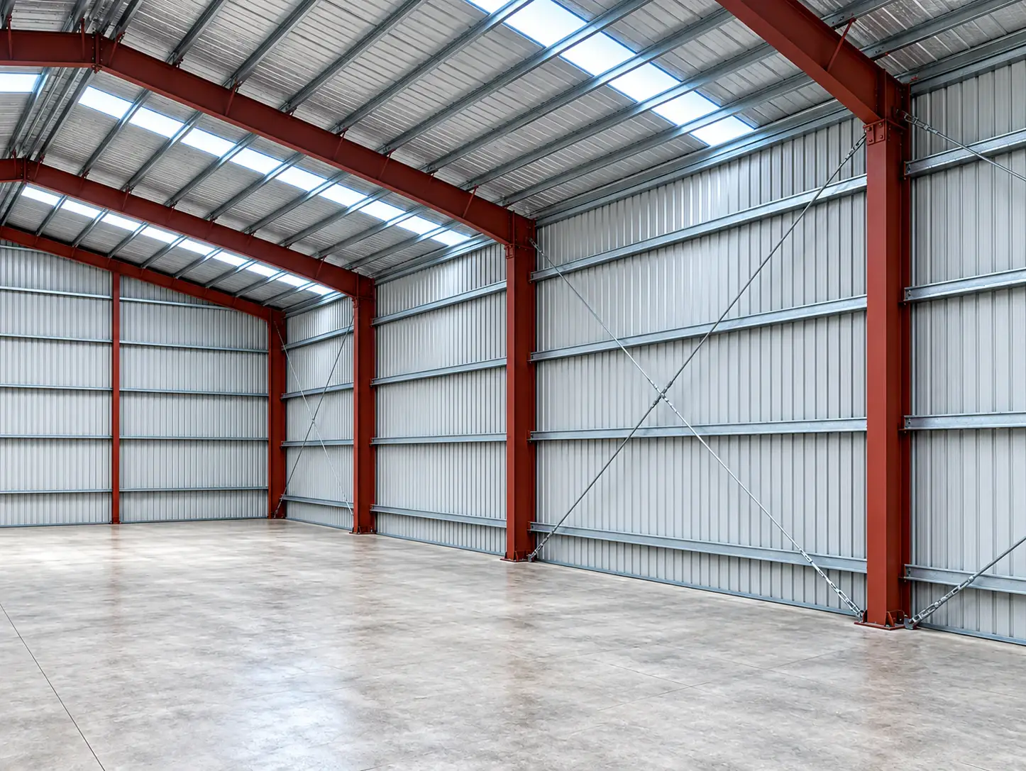
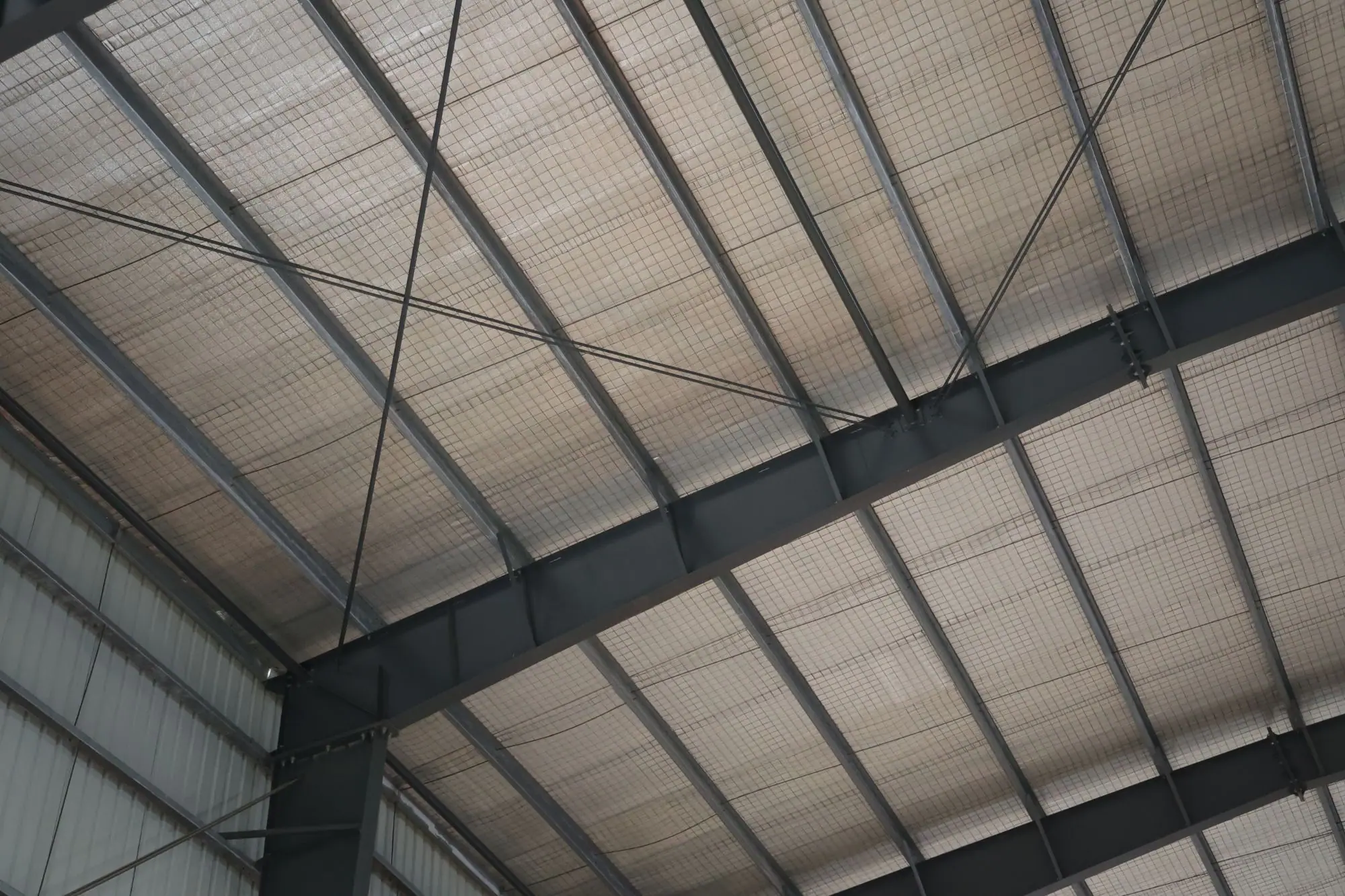
The secondary system spans between the primary frames and carries the cladding. Its members are cold-formed, rolled from thin high-tensile steel strip into Z and C profiles rather than welded from plate, which makes them light enough to lift by hand and stiff enough to span a full bay. They do a second job as well: every purlin and girt braces the rafter or column it bears on, so the secondary system is part of what keeps the primary system stable.
Purlins
Purlins run along the length of the building, parallel to the ridge, at a regular spacing across the roof slope, bearing on cleats welded to the top flange of the rafter in the shop. The roof sheeting fastens to them, so their spacing is set by what the sheet can span under wind uplift and foot traffic. DSI purlins are Z-sections from 345 MPa steel, and a Z nests over the one behind it at every rafter, so the purlins are lapped and bolted through both webs over each support. That turns a row of simple spans into one continuous member, which is stiffer and carries more than the same section spanning bay by bay.
Girts
Girts are the purlins of the walls. They run horizontally between the columns at a spacing set by the wall sheeting, with the lowest just above the plinth and the highest just below the eave strut, spaced around the doors, windows and louvers between. Sidewall girts are the same lapped Z-section as the roof; at the end walls and around openings a C-section is used because it bolts to the face of the post without a lap. Girts are framed bypass, outside the column flange, or flush, between the columns, and headers, sills and jambs of light sections frame every opening.
Eave struts, sag rods and flange braces
The eave strut runs along the top of each sidewall column where roof meets wall, and it is one section doing three jobs: the last girt, the first purlin and a strut tying every frame to the next along the eave. Its flanges are formed to meet the wall and the roof slope so both sheets land on a flat face, and the eave gutter hangs from it. Sag rods between the purlins and girts at mid-span or third points stop the sections rolling and hold them straight until the sheeting is fixed. Flange braces from purlin to rafter and girt to column complete the set.
What makes up the cladding system of a PEB?
The cladding is the building’s skin: the sheeting on the roof and the walls, and every flashing, trim, closure, fastener and gutter that turns loose sheets into a weathertight envelope. It is the system the owner sees and the one that gives trouble first when it is done badly, so its parts are worth knowing by name.
Roof and wall sheeting
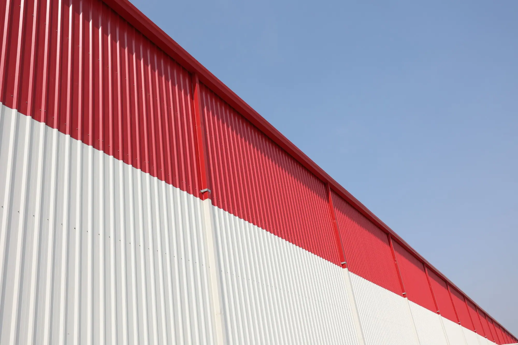
The roof sheet is a trapezoidal profile roll-formed from S550 high-tensile steel, bare Galvalume or colour-coated, in lengths that run from ridge to eave in one piece wherever transport allows. It is laid across the purlins with its ribs down the slope, side-lapped by one rib, and screwed through the crest of the rib into the purlin with self-drilling fasteners under sealing washers. The wall sheet is the same profiled steel fixed to the girts with its ribs vertical, running from plinth to eave where it can. The rib height sets how much water the sheet carries and how far it spans; the high-tensile steel lets a thin sheet do both.
Standing seam roofing
A standing seam roof is fixed without a single hole in the sheet. Each panel sits on concealed clips screwed to the purlins, and its upstanding edges are folded over the neighbouring panel’s edges by a seaming machine on the roof. The clips let the panel slide as it expands and contracts, so long lengths run ridge to eave without end laps and without the fastener holes that leak first on a screwed roof. It is the roof for low slopes, long slopes and buildings that cannot afford a leak.
Liner panels and sandwich panels
Where a finished inner face is wanted, a liner panel of lighter profiled sheet is fixed inside the purlins or girts, with insulation between it and the outer sheet. Where the envelope has to be continuously insulated, as in a cold store or a controlled factory, PUF or PIR sandwich panels, two steel skins bonded to a foam core, replace the sheet-and-blanket build-up on the roof and walls. Both are heavier than a single skin, and the frame has to be designed for their weight and their fixings.
Flashings, trims, ridge caps, gutters and downpipes
Sheets alone do not make a roof. Every edge, change of direction and opening is closed by a flashing or trim folded from the same coated steel: a ridge cap along the top, eave and gable flashings, corner and base trims, jamb, head and sill trims at every opening, and apron flashings where a wall meets a lower roof. Foam closures fill the profile under the ridge and at the eave so wind, dust and birds stay out. Sealant tape in the laps and stitching screws close the side laps. Gutters along the eave and downpipes to the ground take the water, sized for the roof area and the local rainfall, with overflow provision so a blocked downpipe floods the yard and not the floor.
What are the components of a PEB mezzanine floor?
A mezzanine puts a second floor inside the volume the frame already encloses, for offices, stores, light assembly or plant rooms, without adding to the footprint or the roof. Its parts are a small steel building of their own. Mezzanine columns stand on their own base plates and anchor bolts, sharing the foundations with the frame. Mezzanine beams span between the columns, or from a column to a bracket on the main-frame column, and joists span between the beams at a spacing set by the deck. The deck is a galvanised profiled steel sheet screwed to the joists; under a concrete floor it is the permanent formwork, and under a dry floor it carries a chequered plate or a grating. Edge trims, handrails and a staircase complete it.
Because DSI designs the mezzanine as part of the building, its loads are in the frame analysis from the start and its columns are set out on the main-frame bays so nothing lands in a doorway or a crane aisle. Beams and joists are checked for deflection and vibration as well as strength, so an office floor feels solid underfoot.
What accessories complete a pre-engineered building?
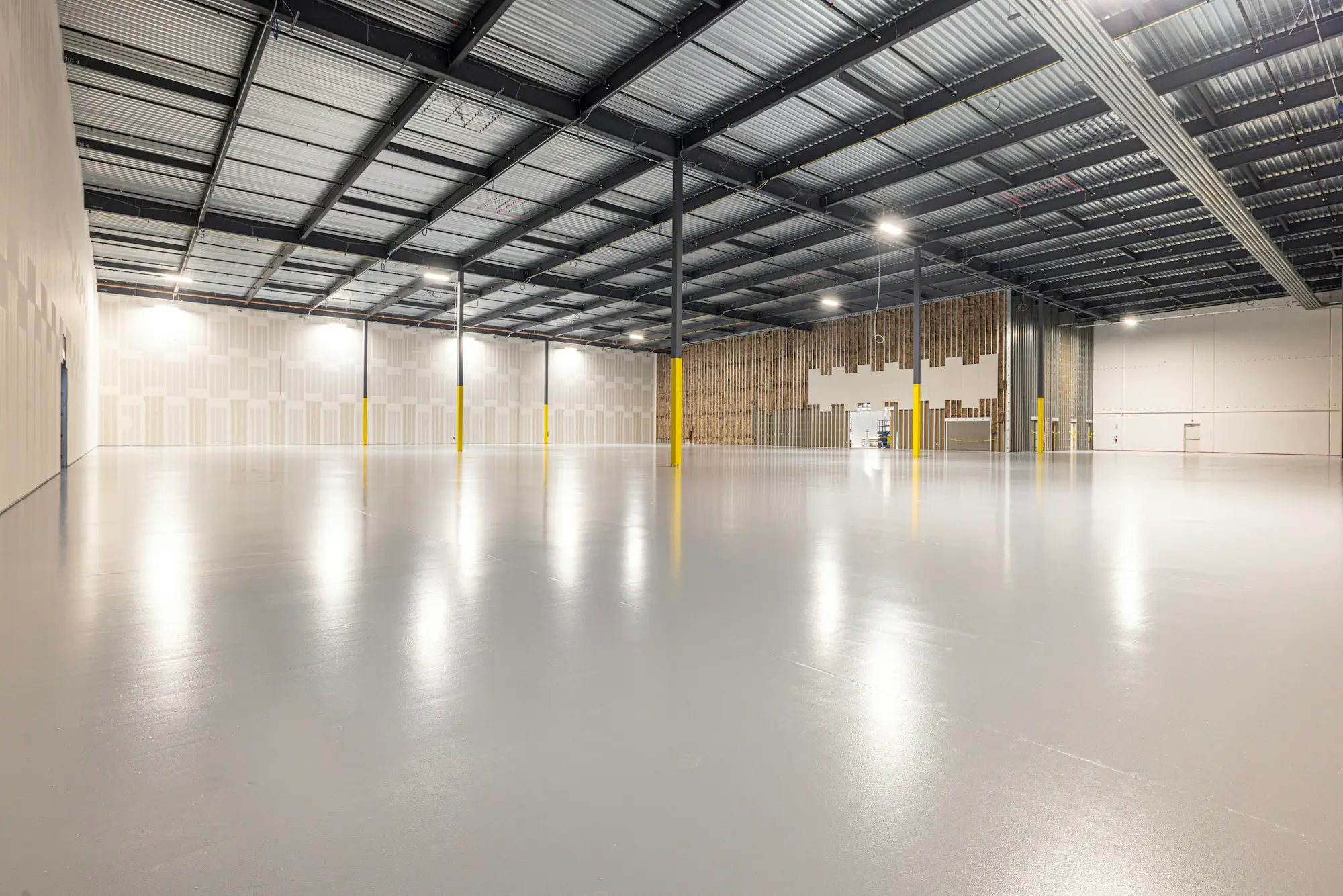
A PEB without accessories is a large sealed volume that is dark, hot and airless. Each accessory is set into the roof or wall cladding and trimmed like any other opening, so it has to be decided with the cladding, when the purlin and girt spacing is fixed, rather than cut in afterwards.
- Insulation: an XLPE foam or fibreglass blanket laid over the purlins and girts directly under the sheet, with a reflective or white facing to the inside, cutting the heat through the roof and quietening the rain. PUF or PIR panels where the envelope must be continuously insulated.
- Turbo ventilators: wind-driven turbines on a base flashing formed to the roof profile, drawing hot air out at the ridge with no power.
- Ridge ventilators and roof monitors: a continuous vented cap along the ridge, or a raised roof section with louvred sides, venting the whole length at once.
- Daylight panels: polycarbonate sheets formed to the same profile as the roof sheet, lapped and fixed like the steel they replace, lighting the floor by day.
- Louvers: frames of angled S-type blades in the wall that let air in low down and keep rain out; the inlet every ridge or turbo ventilator needs.
- Doors and rolling shutters: framed by the girts with headers, sills and jambs, and trimmed with jamb, head and sill flashings.
- Canopies and fascias: a cantilevered roof extension over a door or dock, and a vertical face above the eave or across the end wall that hides the roof line and carries the signage, both designed into the frame.
- Cage ladders and roof access: fixed ladders with a safety cage to the roof and the crane, with walkways where the roof carries plant.
How do PEB components connect to the foundations?
The foundations are not supplied by the PEB manufacturer, but they are designed from the PEB manufacturer’s numbers and they are where every load ends up. The frame analysis produces the reactions at each column base: vertical load, horizontal thrust from the rigid frame, uplift from wind on a light roof, and a moment where the base is fixed. The civil engineer sizes the footings for those reactions and the soil bearing capacity, and casts the anchor bolts in templates to the setting-out drawing. Because a PEB frame is 20 to 30% lighter than conventional steel, the footings are smaller than for a concrete building of the same size, and the saving is real money in the ground.
The interface is the base plate on its anchor bolts, levelled on a grout bed. A survey of the bolts against the drawing before the steel arrives is the single check that keeps erection on its programme, because a column that will not land on its bolts cannot be fixed with a hammer. The floor slab is usually cast after erection, inside the columns, with the plinth and apron done first.
PEB components at a glance
The table lists every component of a pre-engineered building by system, with what it is, what it does and what it is typically made of. Use it to read a general arrangement drawing or a quotation, and to check that nothing has been left out.
Main-frame columns and rafters
- What it is
- Tapered built-up I-sections joined at the knee and ridge
- What it does
- Carry the roof and walls and take every load to the base
- Typical material
- 345 MPa plate, welded; high-strength bolts
End-wall frames and wind columns
- What it is
- Post-and-beam or rigid frames closing each end
- What it does
- Carry the end-wall sheeting; a rigid end wall allows extension
- Typical material
- Built-up or hot-rolled sections
Crane brackets and runway beams
- What it is
- Brackets on the columns carrying beams, rails and stops
- What it does
- Carry an overhead crane to 50 MT along the building
- Typical material
- Built-up beams, crane rail, rail clips
Bracing
- What it is
- Roof and wall X-bracing, portal bracing, eave and ridge struts, flange braces
- What it does
- Carry wind, crane and seismic forces along the building; keep the frames stable
- Typical material
- Rods, cables, angles, built-up portals
Base plates and anchor bolts
- What it is
- Plates welded to the column foot, bolts cast into the footing
- What it does
- Transfer the base reactions into the foundation
- Typical material
- Steel plate; anchor bolts to the design
Purlins
- What it is
- Cold-formed Z-sections lapped over the rafters
- What it does
- Carry the roof sheeting and brace the rafters
- Typical material
- 345 MPa high-tensile strip, galvanised
Girts
- What it is
- Cold-formed Z-sections on the sidewalls, C-sections at ends and openings
- What it does
- Carry the wall sheeting and brace the columns
- Typical material
- 345 MPa high-tensile strip, galvanised
Eave struts, sag rods, flange braces
- What it is
- Formed strut at the eave; rods and angles between members
- What it does
- Tie the frames; hold purlins and girts straight; restrain flanges
- Typical material
- Formed steel, round bar, angles
Roof and wall sheeting
- What it is
- Trapezoidal profile in single lengths where possible
- What it does
- Shed water, resist wind, close the building
- Typical material
- S550 steel, Galvalume or colour-coated
Standing seam roof
- What it is
- Panels on concealed clips, seamed on the roof
- What it does
- A roof with no fastener through the sheet, for low and long slopes
- Typical material
- High-tensile steel, concealed clips
Liner and sandwich panels
- What it is
- Inner lining sheet; or two skins on a foam core
- What it does
- A finished inner face; a continuously insulated envelope
- Typical material
- Profiled steel; PUF or PIR core
Flashings, trims, ridge cap, closures
- What it is
- Folded profiles at every edge, ridge and opening
- What it does
- Seal the envelope where sheets meet or stop
- Typical material
- Same coated steel as the sheet; foam closures
Gutters and downpipes
- What it is
- Eave gutters with brackets and downpipes to ground
- What it does
- Take rainwater off the roof, sized for local rainfall
- Typical material
- Coated steel or GI
Mezzanine beams, joists, deck
- What it is
- A steel floor on its own columns inside the frame
- What it does
- A second level for offices, stores or plant
- Typical material
- Hot-rolled or built-up sections; galvanised deck sheet
Insulation
- What it is
- Blanket under the sheet, or insulated panels
- What it does
- Cut heat through the roof and walls; quieten rain
- Typical material
- XLPE foam or fibreglass; PUF or PIR panels
Ventilators and louvers
- What it is
- Turbo and ridge ventilators, roof monitors, S-type louvers
- What it does
- Move hot air out at the ridge and let cool air in low down
- Typical material
- Aluminium or coated steel on formed base flashings
Daylight panels
- What it is
- Polycarbonate sheets in the roof profile
- What it does
- Light the floor by day and cut the lighting load
- Typical material
- UV-stabilised polycarbonate
Doors, shutters, canopies, fascias, ladders
- What it is
- Openings and extensions framed off the girts and frame
- What it does
- Access, shelter, appearance and roof access
- Typical material
- Steel, framed and clad to match
| Component | What it is | What it does | Typical material |
|---|---|---|---|
| Main-frame columns and rafters | Tapered built-up I-sections joined at the knee and ridge | Carry the roof and walls and take every load to the base | 345 MPa plate, welded; high-strength bolts |
| End-wall frames and wind columns | Post-and-beam or rigid frames closing each end | Carry the end-wall sheeting; a rigid end wall allows extension | Built-up or hot-rolled sections |
| Crane brackets and runway beams | Brackets on the columns carrying beams, rails and stops | Carry an overhead crane to 50 MT along the building | Built-up beams, crane rail, rail clips |
| Bracing | Roof and wall X-bracing, portal bracing, eave and ridge struts, flange braces | Carry wind, crane and seismic forces along the building; keep the frames stable | Rods, cables, angles, built-up portals |
| Base plates and anchor bolts | Plates welded to the column foot, bolts cast into the footing | Transfer the base reactions into the foundation | Steel plate; anchor bolts to the design |
| Purlins | Cold-formed Z-sections lapped over the rafters | Carry the roof sheeting and brace the rafters | 345 MPa high-tensile strip, galvanised |
| Girts | Cold-formed Z-sections on the sidewalls, C-sections at ends and openings | Carry the wall sheeting and brace the columns | 345 MPa high-tensile strip, galvanised |
| Eave struts, sag rods, flange braces | Formed strut at the eave; rods and angles between members | Tie the frames; hold purlins and girts straight; restrain flanges | Formed steel, round bar, angles |
| Roof and wall sheeting | Trapezoidal profile in single lengths where possible | Shed water, resist wind, close the building | S550 steel, Galvalume or colour-coated |
| Standing seam roof | Panels on concealed clips, seamed on the roof | A roof with no fastener through the sheet, for low and long slopes | High-tensile steel, concealed clips |
| Liner and sandwich panels | Inner lining sheet; or two skins on a foam core | A finished inner face; a continuously insulated envelope | Profiled steel; PUF or PIR core |
| Flashings, trims, ridge cap, closures | Folded profiles at every edge, ridge and opening | Seal the envelope where sheets meet or stop | Same coated steel as the sheet; foam closures |
| Gutters and downpipes | Eave gutters with brackets and downpipes to ground | Take rainwater off the roof, sized for local rainfall | Coated steel or GI |
| Mezzanine beams, joists, deck | A steel floor on its own columns inside the frame | A second level for offices, stores or plant | Hot-rolled or built-up sections; galvanised deck sheet |
| Insulation | Blanket under the sheet, or insulated panels | Cut heat through the roof and walls; quieten rain | XLPE foam or fibreglass; PUF or PIR panels |
| Ventilators and louvers | Turbo and ridge ventilators, roof monitors, S-type louvers | Move hot air out at the ridge and let cool air in low down | Aluminium or coated steel on formed base flashings |
| Daylight panels | Polycarbonate sheets in the roof profile | Light the floor by day and cut the lighting load | UV-stabilised polycarbonate |
| Doors, shutters, canopies, fascias, ladders | Openings and extensions framed off the girts and frame | Access, shelter, appearance and roof access | Steel, framed and clad to match |
How the components of a PEB work together
The reason to know the parts is to see the whole. A PEB is one structural system, and the load path runs through every component in order. Rain and wind act on the sheeting. The sheeting carries them to the purlins and girts. The purlins and girts carry them to the rafters and columns, and brace those members while they do it. The frames carry the loads down to the base plates in their own plane, and the bracing carries the along-building loads to the braced bays and down the same way. The anchor bolts pass everything into the footings, and the ground takes it. A crane adds its own loads at the brackets; a mezzanine adds its own at the beams; the accessories add weight to the purlins and holes to the sheeting. Change any one component and the others feel it.
What to check about each component in a PEB specification
- Primary frames: plate grade, frame type, bay spacing, clear span, eave height, and the wind speed, seismic zone and crane loads they are designed for.
- End walls: post-and-beam or rigid, and whether future extension was allowed for in the foundations.
- Bracing: which bays are braced, with rods or angles, and whether portal bracing is used at openings.
- Secondary members: Z or C sections, steel grade, lapped or simple spans, purlin spacing against the sheeting span, sag rods and flange braces included.
- Cladding: sheeting grade, thickness and coating class for roof and wall; screwed or standing seam; liner or sandwich panels where needed.
- Flashings and drainage: shop-formed flashings at every edge and opening, gutter and downpipe sizes for the local rainfall.
- Mezzanine: floor load, deck type, column positions against the layout below, stair and handrail included.
- Accessories: insulation type, number and position of ventilators, louvers and daylight panels, doors and shutters, canopies, ladders, each on the drawing.
- Foundations: base reactions and the anchor bolt setting-out drawing issued to the civil contractor before fabrication.
How DSI designs and makes every component
Darshan Steel Infrastructure designs, fabricates and erects all five systems of a pre-engineered building from its works at Chhattar, Rajkot, Gujarat, with 230+ projects delivered across India since 2018. The primary frames are cut from 345 MPa plate on CNC lines and welded on an automatic beam line; the purlins, girts and S550 sheeting are roll-formed on the same floor, so the frame and its skin leave together; the mezzanine steel, the crane beams, the flashings and the accessories are made to the same drawings and go up with the same crew. The shop runs to management systems certified to ISO 9001, 14001 and 45001 by TÜV SÜD, with inspection records against every mark number.
If you are planning a building, send us the use, the approximate size, the site and what it has to carry. An engineer will come back within one working day with a frame recommendation and a first sizing, with every component on the list above accounted for.